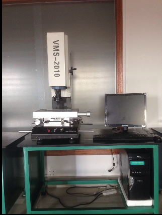
Manual quadratic projector

Product description
Purpose:
The image measuring instrument is suitable for all the application fields with two coordinates as the purpose. It is widely used in the fields of machinery, electronics, instruments, plastics, various precision workpiece and so on.
Instrument features:
Zoom objective lens and cross line generator as a measuring and aiming system;
Image measuring instrument has a variety of data processing, display, input, output functions, especially the workpiece alignment function is very practical;
High resolution 9 - segment constant - power objective lens, change the rate of no need to re - select the scale
The standby R232 interface of the image measuring instrument can be used to process and output the mapping graphics after connecting with the computer
I. standard functions:
1. The product can be taken as a product photo and saved in the computer as a jpeg to form a product gallery
2. The photos saved in the computer are opened and compared in the same picture in the real-time image
3. The graph can be input into AutoCAD to become an engineering drawing
4, the AutoCAD standard engineering drawing can be input into the real-time image, make the AutoCAD engineering drawing and the actual workpiece shape overlap for comparison, so as to find the difference between the workpiece and the engineering drawing
5. Input the jpeg image stored in the previous photo to the real-time image for overlapping comparison with the actual workpiece
6. Dimensions can be marked in the whole picture from a bird's eye view
7, custom circle: according to the customer needs to determine the standard circle, and then the standard circle and the image of the workpiece overlap comparison, so as to find the error between the workpiece and the standard circle
8. Custom line segment: you can define the starting coordinates, length and rotation Angle of the line segment by yourself, and then make overlapping comparison with the workpiece in the image, so as to find the error between the workpiece and the standard figure
9. Set customer coordinates: set the coordinate origin (0,0) on the actual workpiece in the real-time image, and mark the X and Y coordinates of the point at any point on the screen
10. Coordinate labeling: mark the coordinate position of any point on the screen with the self-set coordinate origin (0,0) as the benchmark
11, patent R Angle function: for the current market accurate plane R Angle
12. Measurement: any geometric dimension on the plane can be measured (Angle, diameter, radius, distance from point to line, eccentricity of two circles, distance between two points, etc.)
13. Drawing: the actual shape of the workpiece in the real-time image can be described to form a complete engineering drawing. The drawing method is similar to AutoCAD
14. Labeling: dimensions can be marked on the workpiece in real-time image. Length, Angle, diameter, radius, distance from point to line, eccentricity of two circles, distance between two points, etc
Two, detailed parameters
1 type VMS - 2010
Main body size 600*500*900mm
The size of the platform is 300*250mm
The size of the glass table is 220*160mm
5 the actual working stroke is 200*100*180mm
The main body weight is 75KG
High precision granite base and column for machine bottom
Linear precision (3+L/150) m
9. LED circular ultra-bright cold light source (brightness adjustable)
10 contour LED super bright round lamp (brightness adjustable)
11 calculation and measurement function REICA 2.5d precision measurement system software
12. Analytical force 0.001mm
13. Repetition accuracy 0.002mm
14 CCD SONY chip 1/3 color CCD
15 eyepiece 0.5x (optional 1X,2x)
Objective lens 0.7x ~ 4.5x magnification 20X ~ 120X
Power supply AC90 ~ 264V 50/60hz
18 load of 180 kg
